|
|
|
|
|
|
|
|
|
|
||||||
|
|
|
Radar Schematics [1] In "Radar Schematics" we examine the more important elements of the radar, from an observer's perspective, and lead to a description of the basic architectures that may be found in today's marine navigation radar.
Part 1: The Cavity Magnetron
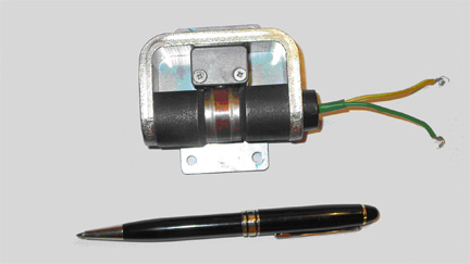
The modern cavity magnetron is so small that it may be slipped into a pocket, and so innocuous-looking that it seems implausible to propose that the outcome of a world conflict hinged on its performance. Yet that was seemingly so, in the view of Admiral Karl Dönitz, commander of German submarine forces from 1939-1945:
"For some months past, the enemy has rendered the U-boat ineffective. He has achieved this object, not through superior tactics or strategy, but through his superiority in the field of science; this finds its expression in the modern battle weapon: detection. By this means he has torn our sole offensive weapons in the war against the Anglo-Saxons from our hands. It is essential to victory that we make good our scientific disparity and thereby restore to the U-boat its fighting qualities." [2]
No doubt physicist A W Hull (1880-1966) would have been astonished, too, had he foreseen the influence of his invention. It started life very simply, as a means to circumvent patents that hampered his company in building amplifiers and oscillators: it might be convenient to control certain classes of vacuum tube device by the use of grids, but it was also expensive, if the General Electric Company was compelled to pay royalties to the patent-holders. To avoid this,
The principle is very simple: a negative voltage applied to a cathode rod located within a more-positive anode sleeve will cause electrons to flow directly from the rod to the sleeve, forming a closed circuit; however, when faced with a magnetic field, electrons behave rather differently, following a curved trajectory - and, if the magnetic field is great enough, they will simply curve back to the cathode from whence they originated. Thus, a variable voltage applied to the coiled electro-magnet acts as a device controller.
* The introduction of slots in the anode wall, with chambers or cavities behind them. As the electron cloud swirls unidirectionally (courtesy of that magnetic field) around the space separating cathode and anode, it flows across the slots, setting up electromagnetic resonances within those chambers and transferring its direct current as wave energy. The depths of the chambers are carefully machined to be directly related to the desired wavelength of the electromagnetic energy.
* Materials science has introduced new cathode alloys that are highly emissive, especially when heated, greatly increasing the potential flow of electrons within the vacuum chamber. The durability of the cathode has been greatly extended, too.
* Early magnetrons were highly unstable [3] in wavelength. Modern systems are much less so, although their wavelengths are still inherently inclined to drift.
* Those early magnetrons had a marked propensity to resonate at undesired wavelengths as well as that intended - indeed, they had nearly as many resonant modes as there were chambers, with no certainty as to which would predominate. Nowadays, this propensity is suppressed, for example by "strapping", where two conductive loops link either the odd-numbered or the even-numbered anode segments between chambers.
Technical Characteristics Magnetrons are used in many systems other than radar, and their use is not entirely confined to the generation of electromagnetic waves. These other uses are beyond the scope of this summary, which is focused on their application to marine navigation radars. In this context alone, the technical characteristics - with which all international civil marine traffic is required by law to comply - are as follows:
* The magnetron is an electro-magnetic pulse generator, triggered by applying a short burst of negative DC voltage to its cathode. Typically, irrespective of wavelength or power output, the output pulse has three to four fixed durations ranging between 50 and 1200 nanoseconds. The bandwidth occupied by a pulse is inversely proportional to its duration; because of mandated bandwidth restrictions to limit interference with other users of the spectrum, pulses shorter than about 50 nanoseconds may not be radiated. Magnetron designs limit the maximum continuous on-time: either the duty ratio [4] is kept low, or special and expensive cooling measures must be taken; and international regulation limits the on-time, also, to aid in mitigating adjacent-radar interference.
* The mechanism by which the magnetron is triggered has undergone considerable change in recent years. In earlier architectures, a magnetron-drive pulse was created in a pulse-forming network comprising an interconnected network of capacitors and inductors; when discharged, the desired output was an approximately rectangular DC pulse, necessary because any current fluctuations at the magnetron interacted with the natural resonance of the device to create spectral distortions. [5] As transistor technology has improved, so has the rectilinearity of the drive pulse, with exceptionally fast rise times and very little magnitude ripple. Today, it is unusual to find a marine navigation radar system employing a pulse-forming network; much more common are high-capacitance field-effect transistors (FETs), and possibly even insulated gate bipolar transistors (IGBTs). The much more rectangular pulses generated by these devices are virtually essential, to conform to treaty goals on out-of-band characteristics for navigation radars.
* There is also an emerging trend, of progressively increasing the magnitude of the drive pulse over the device lifetime, to compensate for gradual depletion and degradation of the cathode, the latter being an inevitable consequence of electron flow within the central chamber. By this means, some radar manufacturers are able to extend magnetron life very considerably: the component manufacturer might specify a guaranteed life of 500 hours, while the radar manufacturer might specify a typical life of 10,000 hours. "Hours" are generally specified to mean whenever the cathode is being heated to promote the emission of electrons into the surrounding vacuum, rather than just the periods when the radar is active.
* Wavelengths and radiated power mandated by international treaty:
3-Centimeter Magnetrons [6]
- A typical 3-centimeter magnetron, by far the most common, has a nominal radio frequency, RF, of 9410 MHz with a manufacturer-assured spread of no more than 30 MHz from its nominal center, and a peak power output of no more than 50 kW.
- Some high-power magnetrons in this band are specified with an RF of 9415 MHz.
- Some older 3-centimeter designs are specified with an RF of 9445 MHz, also with a maximum deviation of 30 MHz from this nominal value. This nominal RF may also be specified for magnetrons in recreational-boat radars that have a peak power output of 1.5 - 2.2 kW; manufacturers of this class of radar typically specify the output as 1.5 kW when very short pulses are radiated.
- The overwhelming majority of 3-centimeter radars, in the Western world, are installed in recreational vessels and utility craft. These vessels have inherently-low capacity for power generation, and this is reflected in their radar designs: magnetron outputs range between 1.5 and 6 kW, with a marked bias towards the lower limit. Peak power outputs beyond this are most likely to be associated with ocean-going craft. It should be borne in mind that magnetron manufacturers typically specify an output range, of from -50% to + 20% of a nominal peak power, and thus the true peak power may be substantially less than documented.
10-Centimeter Magnetrons[6]
- A typical 10-centimeter magnetron has a nominal RF of 3050 MHz, with a manufacturer-assured spread of no more than 30 MHz from its nominal center, and a peak power output of either 30 or 60 kW. - Radars with 10-cm magnetrons are most likely to be installed in larger vessels such as pelagic fishing craft and mercantile traffic. They are highly likely to share mast-head space with 3-centimeter radars.
Physical Characteristics: After many years of refinement, the most widely-used magnetron design in civil marine navigation radars is the strapped-vane version depicted here:
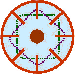
Token Representation of a Strapped-Vane Cavity Magnetron - Plan View This design comprises a hollow copper cylinder, with an even number of anode vanes projecting radially from the cylinder wall towards the center. The vanes are truncated, so that adjacent vanes enclose a cavity whose depth is exactly a quarter of the intended wavelength. Two separate conductive loops connect alternate vanes, to assure common but alternating potential. At the center of the hollow space is an electrically heated and highly emissive cathode. Not shown here are the permanent magnets sitting at either end of the cylinder; nor does the depiction show the probe used in one of the chambers or cavities to collect the electromagnetic energy that arises when the magnetron is activated. The origin of the name is clear: a series of vanes, strapped together in an alternating pattern, forming an even number of cavities. [7]
Behavioral Characteristics
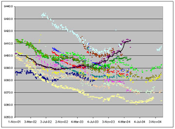
Viewed as a group, there emerges a remarkable degree of similarity in the wavelength behaviors of the systems studied in the course of preparing the MNR Handbook: repeatedly, characterization studies revealed a progressive decline in observed RF at rates of 1-2 MHz per month, often with hints of a seasonal variation superimposed on this decline. The illustration below depicts the long-term RF trends of 14 inventoried systems, each system assigned a unique color for plotting purposes. As can be seen, all but one of these exhibited either one or both characteristics; the one exception is emphasized with a black trend-line representing a moving-average. In the majority of cases, it is obvious that the measured RF was lower, usually by a substantial amount, at the end of the study period than at its commencement, and that the rate of decline was surprisingly consistent between systems. Perhaps less immediately obvious, there was a vaguely sinusoidal variation in the decline that may be correlated to season: broadly speaking, the downward trend reduced or even reversed in cooler months, and accelerated in summer months; this variation was more apparent in some systems than in others. The one oddity emphasized with the black trend-line suffered component failure before the end of the study period.
The origins of these behavioral trends lie in the manner of resonation, which - as noted above - is related directly to the depth of the chambers in the magnetron:
* If this depth is increased, for example by accretion on the anode vane tips of materials ablated from the cathode [8], then the electromagnetic wavelength increases, and the radio frequency - the inverse of wavelength - reduces. A strapped-vane magnetron designed to resonate at 9400 MHz need accrete only 3 microns of cathode material on its vane tips to reduce its resonant frequency by approximately 1 MHz.
* Similar changes in the depths of a magnetron's resonant chambers may be introduced by marked variations in ambient temperature such as those experienced at the test facility, where temperature variations of 100° F between summer and winter may be experienced. If the magnetron is cooled substantially, then its inner chamber will reduce in diameter by a predictable amount that is directly related to the expansion coefficient of the materials from which it is manufactured - copper, in the case of known magnetrons. Reductions in diameter will inevitably reduce the depth of the enclosed chambers, reducing the resonant wavelength and increasing the emitted frequency; in summer, the reverse occurs. Thus, wintertime RF measurements are likely to be higher than summertime measurements, in those systems where the transmitter is embodied in the up-mast components of the radar and thus exposed to climate change.
The Future The future of the magnetron as the core component of the MNR seems assured for now, if only because of its modest cost compared with alternatives, at least where the 3-cm version is concerned. The principal alternative today (others are hastening to market) is a family of recently-developed coherent solid-state system, known as SharpEye; in essence this family replaces magnetron, associated drive circuitry and power-supply architecture in existing Kelvin Hughes' naval and commercial marine navigation radars. Publicity materials for SharpEye, which started to become available in late 2007, described it as "New Technology" with some justification, as it introduced coherent target detection and clutter reduction to the civil maritime domain. Some of its technical characteristics are known: it has a peak power output of 170 Watts, equivalent to 85 kW from a traditional MNR magnetron because of an extraordinarily high duty ratio of around ten per cent, which is strongly indicative of deliberate intra-pulse modulation. Manufacturer literature reveals systems with 3-cm and 10-cm wavelengths, and other trade journals describe "I and F Band radar" - RF-band designators used by NATO, which correspond approximately to 3-cm and 10-cm wavelengths. Discussions with the manufacturer, however, suggest that 3-cm (X Band) systems are seen as probably too expensive for commercial applications at present. Further from the public eye, Japanese manufacturer JRC has also been busy testing an equivalent 10-cm design, its JMA-9172; as of 2010, this design had been type-approved in the European Union but had not yet been included in the JRC product-catalog. More recently, Navico introduced an entirely different technology for the recreational marine electronics market. This technology, implemented in its BR24 Broadband Radar product, which uses an exceptionally low-powered non-pulsed waveform, frequency-modulated continuous wave or FMCW, is considered somewhat immature technically. Nonetheless, experience to date is that the BR24 performs very well at shorter range-scales and modest vessel speeds, that its very low power consumption renders it particularly well-suited to automated 'anchor-watch' operations, and that it appears to continue functioning robustly in close proximity to typical magnetron-based recreational MNR systems. If cost is considered to be a major consideration in the acquisition of a recreational MNR, then the BR24 seems assured of a market; in April 2009, its projected list price was US$1400. From the foregoing, it might seem that the demise of the traditional-design MNR is imminent, but that is certainly not how it appears from reviewing existing manufacturers' product lines. There have been at least 80 new names added to product catalogs over the past two years, and there is no evidence of any slacking-off in product improvement. Many of the new developments, especially those focused on recreational and service craft, now refer to "high definition" or "digital" when describing their advantages over earlier designs. However, as might be expected, there has also been a considerable rationalization of older product lines, with perhaps as many as 200 individual models no longer available from their original manufacturers. The picture, then, is of an industry undergoing change and rationalization; the direction of that change has two strands: the implementation of coherent pulsing techniques that were previously confined to military and naval (and expensive) systems, from traditional "high-seas" manufacturers; and the adoption of very low peak-power FMCW systems, so far only by "new-start" manufacturers with no background in conventional radar manufacture. Footnotes: |
|
| ||
|
|
|
|||||
|
|
|
|||||
|
|
|
|||||
|
|
|
| ||||
|
|
|
|
|
|
|
|
|
|
|
|
|
|
| |
|
|
|
|
|
|
|
|