|
|
|
|
|
|
|
| |||
|
|
|||||||||
|
|
|
Radar SchematicsPart 2: Antenna Designs The Telemobiloskop Revisited
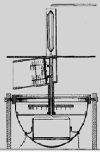
It is hard to overstate the extraordinary foresight of the then 22-year-old Christian Huelsmeyer. His post-war efforts to have early patents recognized in Britain were overturned, on the grounds that his device did not measure range (a somewhat specious argument, it would appear, since the British name for the technology was Radio Direction-Finding, and his device clearly determined direction). Nonetheless, with considerable engineering percipience, he included: mutual interference suppression circuitry, decades before another radar system would exist to cause such interference; a directional VHF antenna array amazingly like the Yagi-Uda invention that would be patented two decades later; a motor-driven array that took more than three decades to be mimicked; and a gimbal arrangement for antenna stabilization that took almost 100 years to re-appear in small-craft radars. The system operated at a wavelength of about 1 meter (around 300 MHz), and employed two antennas, aligned horizontally and displaced vertically on a common spindle. The transmit antenna was situated almost completely inside a focusing cone that effectively concealed its elements from all but directly in front, and, very importantly, protected the receive antenna from the broadband spark-gap transmitter. The receive antenna was located in a near-hemispheric parabolic dish, with most of the antenna elements visible from side view. The US patent application tells little of the processes or materials used, but the system was demonstrated to have a range of 3 km, and Huelsmeyer claimed that he was ready to demonstrate a 10 km capability. Alas, the next full demonstration of the system had to await the invention's centenary - when it worked exactly as Huelsmeyer had shown.
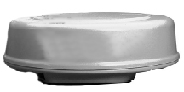
Today's antenna systems are as different from the truncated parabolic dish of the early SG radar installed in USS Semmes as that antenna was from the Telemobiloskop array, courtesy of more than a century of research into the use of waveguides for the transmission of RF energy between antennas and transceivers. First conceptualized in 1892 [2], these copper-lined hollow tubes have been prominent in microwave radar design since the 1940s and their use is widespread in marine navigation radars for connecting between the RF circuitry and the antenna. Waveguide theory is beyond the scope of this guide to marine navigation radars, but there are several key characteristics essential to understanding their part in radar topology: • First, although waveguide transmission lines are conceptually somewhat similar to the familiar coaxial cable used to connect home satellite and cable receivers to the signal input, they are much better-suited to high-power RF distribution, partly because the conducting surface of the waveguide is much greater than that of the thin copper wire at the heart of the coaxial cable, and partly because the electromagnetic waveform is confined within the waveguide, greatly reducing transmission leakage. • Conversely, they are largely impractical for RF transmission at lower frequencies, because their width needs to be at least a half (optimally, around 7/10ths) of the wavelength for transmission, rendering them physically impractical for use below around 1000 MHz, equivalent to a wavelength of 30 cm and generally taken as the lower limit of the microwave band. • They are also rigid, requiring special joints both to connect lengths and to make physical turns. Also, they may be very expensive, with some designs plated with precious metals to improve conductivity - thus, on both cost and performance grounds, it is most effective to have the transmitter, receiver and antenna collocated. • They have a restricted bandwidth - a waveguide designed to transmit a 3-centimeter wave will severely distort a 10-centimeter wave. In early implementations of marine radar, the waveguide served as the interface between the RF elements of the transceiver units and the antenna, which was typically a flared horn at the focus of a parabolic reflector. There are still examples of such radars at sea, most often with mesh-type reflectors rather than the solid reflector that was used in the SG radar; but they have almost entirely disappeared from usage in civil designs [3], replaced by structures that are much lighter, more easily manufactured and much less vulnerable to harsh weather conditions. Their place has been taken by two visually-different styles of antenna: a squat cylinder or radome that is sometimes referred to as a hatbox antenna; and a relatively-long, narrow, rectangular structure with many names.
The Typical Rectangular Array • The attractiveness of the paraboloid as a radar antenna element is its key characteristic: All radiations emanating from the point of focus (the real antenna, often a waveguide horn) and illuminating the parabolic surface are reflected outwards in such a manner that, when observed at any substantial distance, they have a common phase. Similarly, all emanations from a distant point that illuminate the surface of the paraboloid will be reflected to the point of focus, again with a consistent phase. This means that they are additive in nature, making the paraboloid a nearly ideal antenna for both transmission and reception. It has shortcomings, such as aperture-blocking, where the antenna at the point of focus obstructs the reflected wave, but is still popular for many applications. • Modern antennas in marine navigation radars mimic that key characteristic of the paraboloid by using an array of antenna elements, physically separated such that, when transmissions combine in free space they do so with a common phase; and when a wave-front illuminates the array from a distant point, it combines within the transmission line, again with a consistent phase. These array-based antennas do not suffer from aperture-blocking, but have other potentially unwelcome characteristics. In particular, they may be especially sensitive to changes in wavelength. The physical separation of antenna elements is fixed, as are the signal path-lengths, and so the combinatorial benefits are available only over a very small range of wavelength values - the antenna has an inherently narrow bandwidth compared with the paraboloid. When this range is exceeded, the free-space combining of radiated waves may become primarily destructive, rather than additive, creating nulls and unwanted lobes and degrading the directivity of the antenna system.
|
|||||||

|
Peeking under the lid of an orbiting "patch array" antenna |
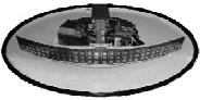
It is most unlikely that the design of the array will be known, as only rarely do manufacturers disclose the specific type of radiator enclosed in the hermetically-sealed radome. Nonetheless, it is perfectly possible to make some assertions about the radome antenna, without ever seeing inside:
-
Physical dimensions influence beam-forming capability, in a predictable manner. A long horizontal dimension correlates to a narrower horizontal beam, while a low vertical profile correlates to a wider vertical beam. Thus, a squat radome antenna will produce a fan-shaped beam, the dimensions of which may be approximated from measurement.
-
Power and size also correlate: the larger the radome, the greater its power-handling capacity is likely to be. Marine navigation radar domes vary in diameter from around 12 inches to around 25 inches, and their peak power outputs range from 1.5 kW to around 4 kW, with a very few being capable of 6 kW.
Two last notes, regarding the scanning behaviors of some radome-based radar systems:
-
They are generally installed on vessels subject to considerable pitching, rolling and heeling; their fan-shaped beam may illuminate the heavens at one moment and the imminently-overwhelming wave at the next. To compensate for this, in recent years there has been a small but growing trend to mount the radar on a gimbaled platform, keeping it somewhat stable and, after a lapse of around 100 years, resurrecting a fundamental feature of the 1904 Telemobiloskop design.
-
Until fairly recently, a radome-enclosed antenna would employ a nominally fixed rate of rotation, around 24 revolutions per minute. Now, it is increasingly common for these radars to exhibit more than one rate, automatically switching to other, faster rates either when a very short range scale is selected by the user, or when the craft's speed exceeds some predefined threshold. Typically, these faster rates range between 30 and 45 revolutions per minute.
The Rectangular Array
They may have many names, but these are rarely if ever referred to as "rectangular arrays." In the manufacturing world, they are commonly known as open arrays, to distinguish them from the radome-enclosed antennas. More widely, they may also be referred to as linear arrays, giving some clue to their topology; but most revealingly, they are often referred to as slotted waveguides or leaky waveguides, an apt description.
Early microwave radars used the waveguide as a transmission line to deliver RF energy to a horn antenna - essentially a flared section of waveguide that distributes energy across the arc of a paraboloid - but the concept of direct radiation from small apertures within the transmission-line waveguide was quick to emerge, and was realized in practice in the early 1950s. It may seem odd that a hole in a conducting surface may function as an antenna, and yet that is precisely what happens: the hole interrupts the currents flowing on the internal surface of the waveguide and some of the energy escapes ("leaks") into free space.
Whether the holes are narrow slots cut into the wall of a section of waveguide, or apertures cut into a conducting plate of a radome antenna, the effect is the same - radiation. In the reverse direction, electromagnetic waves entering the slots set up currents on the conducting surface. When directivity is required, as it is in radar applications, the manufacturer must arrange a succession of slots in such a fashion that their effect is combinatorial, as described earlier in this section. Properly spaced, the slots can be used to form a focused beam, essentially broadside to the axis of the waveguide; and received energy of the right wavelength and from that broadside direction will maximize the current delivered to the receiver.
Some key characteristics of the slotted-waveguide antenna:
• They are very attractive as antennas in marine radars, because of their very low profile compared with paraboloids, making them much better suited to harsh environments.
• They are relatively inexpensive to manufacture, although some designs are more complex than others. They are also hermetically sealed, and have an electromagnetically transparent but optically opaque material concealing the internal structure.
• There are two fundamental designs: end-fed and center-fed, the latter becoming increasingly popular as it involves a shorter signal path between the transceiver and the array.
• They may have substantially greater power-handling capacity than the radome antenna, limited by the dimensions of the waveguide. In marine navigation radars, it is not at all unusual for a 10-cm antenna to be rated at a 60-kW capacity, and some naval variants may exceed 150 kW capacity.
• Antenna sizes vary considerably. At the low end, there are versions as short as 2 feet (0.6 m) in length, designed for recreational and service craft; at the other end of the scale, as long as 14 feet (4.3 m). Somewhat as with the radome antenna, size and power generally correlate: smaller antennas tend to have low peak power output, and very high peak powers are generally associated with large antennas.
• It is quite common for the transceiver to be incorporated into the pedestal unit containing the motor drive for these antennas, particularly at the lower end of the range of power outputs. Higher-power transmitters are somewhat more likely to be located in a separate unit, connected to the pedestal unit by waveguides.
• Antenna rotation, especially with 10-cm radars, is influenced by the ship's power supply. Manufacturers routinely disclose that the same motor turns an antenna at one rate with a 60 Hz supply, and at a different rate with a 50 Hz supply.
• It is clear from the antenna dimensions that a fan beam should be radiated. However, the much larger antennas are well-suited to operation at 10-cm wavelengths, and so it becomes important to know which operating wavelength is being used (3 or 10 cm), in order to estimate the dimensions of the beam. Short wavelengths produce narrower fans than longer wavelengths: a 12-foot (3.7 m) antenna will have a horizontal beamwidth of around 0.6° if its operating wavelength is 3 cm; a 10-cm antenna of the same length will have an horizontal beamwidth of around 1.8°.
• As noted previously, these antennas may be sensitive to changes in wavelength. In fact, they suffer from a characteristic known as "squint" - a small divergence from the intended broadside radiation that is caused by variation in wavelength. Even the small variations that a well-performing magnetron exhibits may affect the performance of the antenna, and large variations may cause a substantial breakdown, both in the intended lobe structure and in the radar components, as well as placing the operator at risk of contravening national and international regulations.
• What is not visibly clear from the antenna dimensions is a property of the slot as a radiating element: the polarization of the wave that passes through the slot will be orthogonal to the slot orientation, whereas in a dipole the orientation of the dipole and the plane of polarization are the same. The slots cut into the wall of a marine navigation radar's waveguide are usually orthogonal to the horizontal axis of the waveguide itself, and so the antenna is horizontally polarized; this need not be the case with radome antenna systems, although it usually is.
There is further aid in the characterization of slotted-waveguide antennas, found in the form of international regulations governing the capabilities of radar systems used on civil vessels engaged in international traffic. These regulations, which do not cover smaller craft and recreational vessels, mandate that a radar must scan the horizon at a rate of no less than 20 revolutions per minute, that it have an angular discrimination no worse than 2.4° and that its detection performance be identical throughout a roll of + 10°; further regulations governing radar performance in high-speed craft such as hydrofoils mandate a scan rate double that of the basic law. From these:
Footnotes:
[1] Scientist John Pierce (1890-2002), who is credited with many "firsts" in 20th Century technology and who concocted the name "transistor" for a colleague's world-changing invention.
[2] By English physicist Joseph Thompson, better known for his discovery of the electron.
[3] The PIN 524 navigational radar, by Bharat Electronics Limited, India, uses a parabolic mesh reflector.
![]()