|
|
|
The MNR Handbook
Case Studies
This Section links to other chapters, with each chapter focusing on an individual MNR manufacturer. Each chapter explores the history and partnerships of a manufacturing company and then describes in more detail its present-day product line, grouping these where appropriate so that the reader will appreciate the parametric relationships variation that may be observed in radiated data. There are chapters describing the following corporate MNR manufacturers:
Consilium Navigation
Furuno
Garmin
GEM Elettronica
Japan Radio Company, JRC
Kelvin Hughes
Koden Electronics (including Anritsu, Lowrance, Nobeltec, Northstar, SI-Tex and Simrad)
Navico
Raymarine
Raytheon Anschutz
SAM Electronics (ex-STN Atlas)
Sperry-Decca
Case Study Observations
Background
The chapters covering Furuno, JRC, Koden Electronics and Raymarine are substantially more extensive than others, because they include long-term studies of systems held on the inventory of the Naval Research Laboratory for various overlapping periods between November 2001 and November 2004. Most of the systems studied were X-band equipments suited to non-IMO vessels such as fishing, utility and recreational craft, in up-mast configurations with a DC voltage supply in the range 12-24 volts; in some instances, this DC power was provided by rectification of shore supplies, and in others via an external battery that was kept charged.
For the study, observations of radiated signal data were derived aperiodically from an IFM-based system, automatically characterized, identified by a qualified operator, and catalogued in spreadsheets. In some instances, radiated signal characteristics were too complex to be fully catalogued, specifically those related to complex pulse interval behavior; in those instances, the operator logged as many characteristics as circumstances would allow. Thus, any one observation might comprise a restricted representation of reality; over multiple observations, however, the totality of a complex behavior might be discerned from the numerous individual observations.
The radars involved in the long-term study [1] were not usually amenable to remote control, and physical access required considerable travel from the observation facility; in consequence, the radars generally operated in a given mode for long periods. Also, since the radars overviewed a seaway spanning several nautical miles, it was unusual for them to be operated on very short range-scales; for most of the time, they were left to operate on what the radar manufacturer might term Medium or Long range-scales, ranging upwards from around 3 nautical miles. Because of the natural human desire to see over the horizon, operation in Short Range modes, characterized by high pulse rates and pulse durations less than 150 nanoseconds, was quite uncommon. To accommodate this natural tendency on the part of radar users, behavioral snapshots comprising pulse-level data from the IFM system were also obtained when possible, and their characterizations incorporated into the evaluation of individual systems.
Finally, it should be noted that, from time to time, individual systems suffered from component failures or were temporarily adapted to satisfy the requirements of other trials. For example, a new magnetron might be installed temporarily to test other sensors; or an antenna drive-belt might need to be replaced because of wear. Although they might help account for some of the abrupt irregularities noted, records of these maintenance transactions were not available during the studies for this section of the handbook. Caution is therefore advised in interpreting short-term behaviors, and it should be noted that, with the exception of pulse-train behaviors, the analysis which follows focuses deliberately on behavioral trends rather than specific events.
Analysis
Radio Frequency
-
All of the radars studied exhibited small short-term RF variabilities; over a span of weeks, the measured RF might vary by perhaps 2-3 MHz, but more substantial variations in that span were quite uncommon.
-
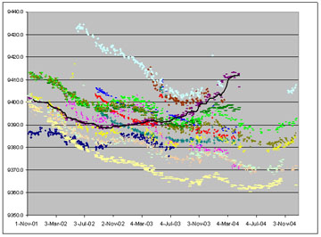
An almost-universal characteristic of the radars studied, however, was a long-term behavior: with only one exception, all of the radars exhibited a long-term downward trend in RF, with rates ranging between 0.5 and 3.0 MHz per month.
click for Large picture
-
In a typical scenario, the RF measured at the beginning of the study would be around 9410 MHz; over the next 24-30 months, it would reduce to around 9375 MHz, with the sharpest reductions occurring early in the span (one of the diagrams produced for the study of a SI-Tex T-295 radar system, provides a good illustration of this trend).|
-
After the RF low-point had been reached, it was quite usual to see a gradual reversal of the behavior; however, none of the preserved data sets showed a complete reversal, and anecdotal evidence was provided that it was quite common for magnetron failure to occur within a short span after the minimum point had been reached.
-
Given the observations, the span of time over which the behavior projected, and anecdote, it appears that this trend is a common consequence of magnetron-ageing.
-
Beyond the long-term trend in RF behavior, there were several instances where an apparently-seasonal influence was noted (again, the diagram in the SI-Tex T-295 provides pictorial evidence). This influence took the form of a somewhat sinusoidal variation in the downward trend of RF, with wintertime measurements generally somewhat higher than in the preceding summer, and often substantially higher than in the following summer.
-
The underlying causes of this apparent behavior were not readily discernible from the preserved data. However, in a subsequent cool-weather test, the chassis temperature of one captive system was deliberately varied between 32 and 90°F, twice in a span of ~90 minutes. During this short test, the radar repeated much of the patterned variability of RF noted over yearly cycles, but in a greatly compressed span of time.
-
The test, then, combined with the study measurements, suggests strong coupling between ambient temperature and a single system's RF, when that system is an up-mast configuration. If the coupling is real, it reveals itself as reduced RF at higher temperatures, with differential-dependent variations of up to 12 MHz over the range 32-90�F; the long-term study data suggests a much smaller variation, typically no more than 5 MHz.
-
This aspect of magnetron behavior is also discussed under Pulse Duration. Broadly:
-
Observed pulse durations averaged over the study period were much as advertised by radar manufacturers, and often indistinguishable from claimed characteristics.
-
Occasionally, it was noted that the PD declined progressively over the span of study, and in some instances became more erratic in time (a diagram resulting from the study of a Raymarine SL-74 system, provides a representative illustration).
-
There were also occasionally hints of apparently-seasonal variation similar to that noted for RF, although on a greatly muted scale (see analysis details for the Furuno 1943C radar system for a good illustration):
-
Excluding the progressively-erratic behaviors noted above, it was rare for any one system to deviate by more than 100 nS from its nominal value - so small that ordinarily it would be overlooked.|
-
Nonetheless, PD behavior was explored during the cool-weather test described for RF behavior, and a small but distinct variation appeared to correlate with deliberate changes in temperature.
-
More specifically, PD reduced from around 0.83 μS when the radar chassis was cold, to around 0.77 μS when it had been heated to 90°F - a very subtle change, noted during an ad hoc test under non-laboratory conditions.
Scan
-
As with radio frequency, it was quite common to note the apparent coupling between scan periodicity and season, with slow scans seeming to correlate with colder weather. The most persuasive illustration of this was obtained during review of data from a SI-Tex T-195 radar system, which varied its scan cyclically between 2.4 and 2.8 seconds. In general, it appeared that the radars studied employed periodicities that were most like their documented scan in summer, and least like in winter.
-
However, the correlation between season and periodicity was much less persuasive during the cool-weather test described above. It is possible that the antenna slows down as temperature declines, but the reverse cannot be claimed: the slowest periodicity observed occurred during a heating phase, rather than a cooling phase, which is entirely at odds with the study-data. The test was not conducted under rigorous control; even so, a clear correlation between scan periodicity and ambient temperature was not demonstrated.
Pulse Rates
-
No published manufacturer documentation identifies in any detail the nature of the inter-pulse modulation characterization, for any of the systems documented in this handbook.
-
Kelvin Hughes is somewhat unusual, in that its literature discusses in broad generalizations the capacity of its radars to vary pulse rates within a range and to superimpose "noise modulation" on the pulse train.
-
In all other instances, literature will at best identify only a nominal pulse rate; in some instances, not even this is provided, and tangential methods must be used to overcome corporate coyness (e.g. by tracking down certification authorities' type-approval documentation).
-
Perhaps surprisingly, then, the measured pulse rates were usually very close to the rates gleaned from literature searches; indeed, even in the very worst case noted, the average pulse rate was within approximately 10% of the declared PRF, differing by 50 Hz from a documented PRF of 600 Hz.
-
The tables provided in the Case Studies may thus represent a useful guide to system identification from measured behaviors.
Inter-Pulse Modulations
None of the systems held by the NRL exhibited a simple, uncomplicated pulse-train; in every instance, some form of interval modulation was employed. At its simplest, this was a 2-element 2-position stagger; at the most complex, a 255-element discrete jitter or stagger was used. In every instance, there appeared to be distinctive features by which the radar origin might be identified, although it may take a considerable volume of measurements for some of these to appear to the observer. These distinctive features were as follows:
Furuno:
-
Furuno radars employed either of two 16-element 16-position staggers, described in detail in the Furuno case studies.. The choice of stagger behavior may be generational, with older radars tending to use one form, and newer (or updated) systems using some variation of the second.
Irrespective of the stagger sequence, the Furuno radars studied are readily recognized as such, by simple steps:
-
The PRI range-base is the smallest difference between sorted pulse-interval values;
-
The individual pulse intervals represent the 240th through 255th multiple of the PRI range-base;
-
Division of the PRI range-base by a smaller value, 0.10296 μS, will produce an integer result if a 77.7 MHz clock is used, and the presence of a 77.7 MHz clock indicates a more modern design;
-
Discrimination between the two stagger patterns is readily achieved, both visually and by comparison of alternate pulse-interval values.
JRC:
-
Radars manufactured by JRC, including some Raymarine models (the Raymarine
R21XX and possibly the parametrically-indistinguishable R10XX, R11XX, R20XX, R40X, R41X and R41XX), used a slightly unstable 2-element 2-position stagger.
-
Although the stagger may be slightly unstable, there was a constant relationship between the short and the long interval, that is a stagger ratio of 3:4.
Koden:
Raymarine:
-
The SL-72 and SL-74 systems both used a complex 75-element stagger, with an unvarying PRI range-base of 0.407 μS. The total PRI spread, in all PRI ranges, was approximately 32 μS, sufficient to encompass 80 uniformly spaced elements, but five of the potential elements were never used. Unusually among the characterized radars, these systems used pulse rates that manufacturer documentation ascribes to an entirely different product line, rather than the rates ascribed to the Pathfinder series to which they belong.
-
The RD218 and RD424 systems also used a complex 75-element stagger with a total PRI spread of approximately 32 μS and, like the PRI distributions of the SL-72 and SL-74, there were five potential elements that were never used; the same five elements, in every observed mode of all four radars.
-
The RD218 and RD424, although somewhat similar to the SL-72 and SL-74, exhibited a very distinctive feature: the PRI range base was an order of magnitude smaller, at approximately 0.047059 μS, and PRIs were spaced non-uniformly at intervals of either the 9th (usually) or 8th multiple of the PRI range base. Also unlike the SL-72 and SL-74, their behaviors precisely matched manufacturer specifications, although they did not exhibit all documented characteristics.
Sperry Marine:
-
The Bridgemaster E systems observed in the study employed a complex 66-element discrete jitter or stagger, with a mode-independent PRI range-base of 0.610250 μS. It is postulated that individual systems may have manufacturer-assigned sets of PRI values for the purpose of disambiguation or interference-reduction between adjacent Bridgemaster radars.
[1] A much shorter study, in 2009, examined the pulse modulation characteristics of newly-inventoried Raymarine RD218 and RD424 systems. The Raymarine section has been updated because of these later studies, which uncovered a highly complex but ultimately repetitive and predictable 75-element PRI stagger pattern that had defied previous efforts to penetrate and had been categorized as a pseudo-random discrete jitter. This behavior is described in more detail in our subscriber-accessible lockbox, here. A review of the earlier investigations suggests that this behavior may be common to several Raymarine designs.
|
|
|